|
|
|
Who's Online
There currently are 5780 guests online. |
|
Categories
|
|
Information
|
|
Featured Product
|
|
|
 |
|
|
There are currently no product reviews.
 ;
This manual is a complete guide, including later additions. It has all the necessary information about the replacement items. The material quality is great to read.
 ;
This manual is very helpful, correct shematic diagram, and good exploded view.Perfect!
;
Alte gescannte Servicepläne sind oft doch etwas undeutlich . Stromlaufpläne werden auf mehrere DIN A4 Seiten aufgeteilt. Alles ziemlich umständlich und zeitaufwendig. Aber mit etwas Mühe geht alles.
;
Great item, high resolution, detailed, very easy to work with.
;
fast delevery of the manual and very complete manual, now my Akai works again, will buy again, thanks.
MODEL: WT-42311 / WT-A42
ANODE LEAD REMOVAL
CAUTION: To prevent damage, the following procedure must be used when removing an Anode Lead from the Flyback Transformer.
1) Push the Anode Lead down.
2) While holding the lead down rotate the lead 90º counter clockwise.
3) Carefully remove the Anode Lead from the Flyback Transformer.
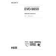
CRT REPLACEMENT
1. Removal of the CRT
Caution! High voltage should be completely discharged prior to CRT removal. Since the CRTs receive high voltage from the Flyback transformer, discharge the CRTs by shorting the open end of the respective high voltage cable to chassis ground.
1. Refer to Cabinet Disassembly and remove the Light Box Assembly. 2. Remove the three Anode Lead Wires from the Flyback transformer and discharge the CRTs. (Use the above procedure) 3. Unplug the three PCB-CRTs. 4. Remove 4 screws "a" retaining the Optical Unit. [Figure 1] 5. Remove 4 screws "b" retaining the Lens of the respective CRT 6. Lift the Optical Unit from the Light Box and set it lens down on a flat surface. 7. Remove 4 screws "c" retaining the CRT. [Figure 2] Note: DO NOT loosen the spring loaded screws. Doing so will break the seal between the C-Element and the # 6 Lens, causing leakage of the CRT Coolant. 8. Remove the Deflection Yoke from the neck of the CRT. [Figure 3]
Figure 1 Page 12
|
|
|
> |
|